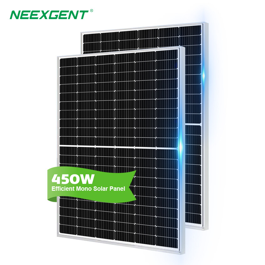
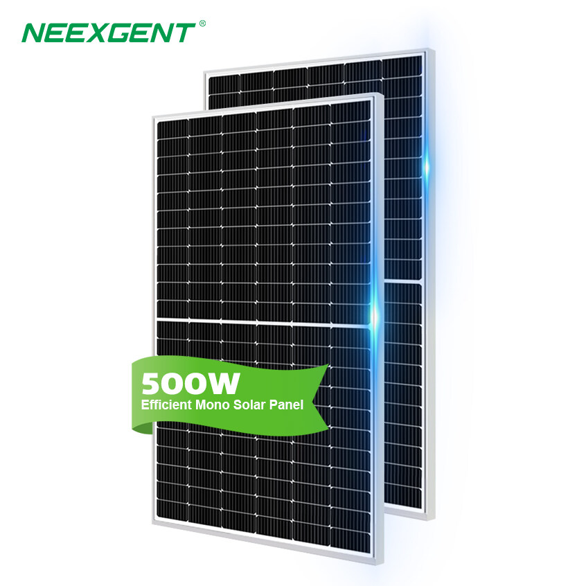
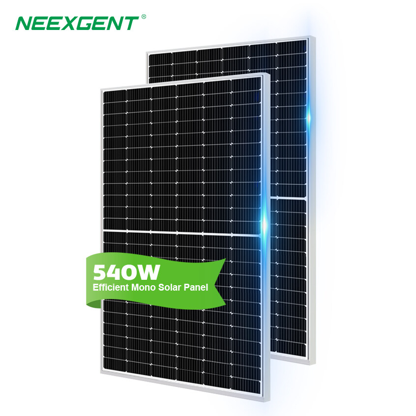
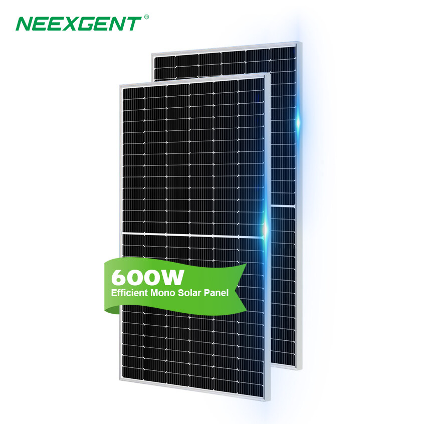
A well-designed 24V solar power system must do more than connect a solar panel, battery, charger, and inverter. The important part is making sure each device operates within the correct voltage range, charging sources work together properly, and high-current circuits are protected against overload and short circuits.
The diagram below shows the physical power paths. This article focuses on the design decisions behind those connections.
⌁
Shore Power or Generator
AC →
↯
Converter / Charger AC to 24V DC
Charge →
▣
24V Battery Battery Bank
← Swipe horizontally to view the full diagram →
A 24V battery system is often a practical choice when the installation has a moderate or high power requirement.
For the same power output, increasing the DC system voltage reduces current.
The basic relationship is:
Current = Power ÷ Voltage
Example Load: 1,200W
12V System
1,200W ÷ 12V
≈ 100A
VS
24V System
1,200W ÷ 24V
≈ 50A
Same power, twice the voltage, approximately half the current.
Actual inverter current will be slightly higher because of conversion losses.
Lower current can make it easier to control voltage drop and reduce the amount of extremely heavy cabling required for high-power equipment. This is one reason 24V systems are common in larger RV, marine, cabin, mobile, and off-grid installations.
A 24V battery bank does not mean the solar panels must always produce exactly 24V.
With an MPPT solar charge controller, the solar array can operate at a higher voltage than the battery bank. The controller converts the available panel voltage into the charging voltage required by the battery.
This makes series-connected solar panels useful because higher PV voltage can reduce current on the solar side of the system.
However, the total open-circuit voltage of the solar array must remain below the maximum PV input voltage of the charge controller, including the voltage increase that can occur in cold weather.
The controller should therefore be selected according to both:
The charge controller must be large enough to handle the expected charging current from the solar array.
A simple preliminary estimate can be made by dividing the solar array wattage by the battery charging voltage.
For example, a 1,000W solar array charging a nominal 24V battery bank may produce roughly 35A to 40A of charging current depending on battery voltage, solar conditions, and controller efficiency.
A controller with sufficient current capacity and suitable safety margin should be selected.
The exact charging voltage must also match the battery chemistry.
Lead-acid, AGM, gel, and lithium batteries do not necessarily use the same absorption, float, or termination settings.
Battery capacity should be determined from the amount of energy the system needs to supply rather than inverter wattage alone.
Battery energy is commonly expressed in watt-hours:
Watt-hours = Battery Voltage × Amp-hours
Example Battery Capacity
Battery Voltage 24V
×
Battery Capacity 200Ah
=
Total Energy 4,800Wh
Battery energy is calculated by multiplying system voltage by amp-hour capacity.
This does not mean all 4,800Wh should necessarily be used.
Available energy depends on battery chemistry, recommended depth of discharge, temperature, battery-management limits, and conversion losses.
Lithium batteries can usually provide a larger usable percentage of their rated capacity than traditional lead-acid batteries, but they also require compatible charging equipment and a correctly configured battery-management system.
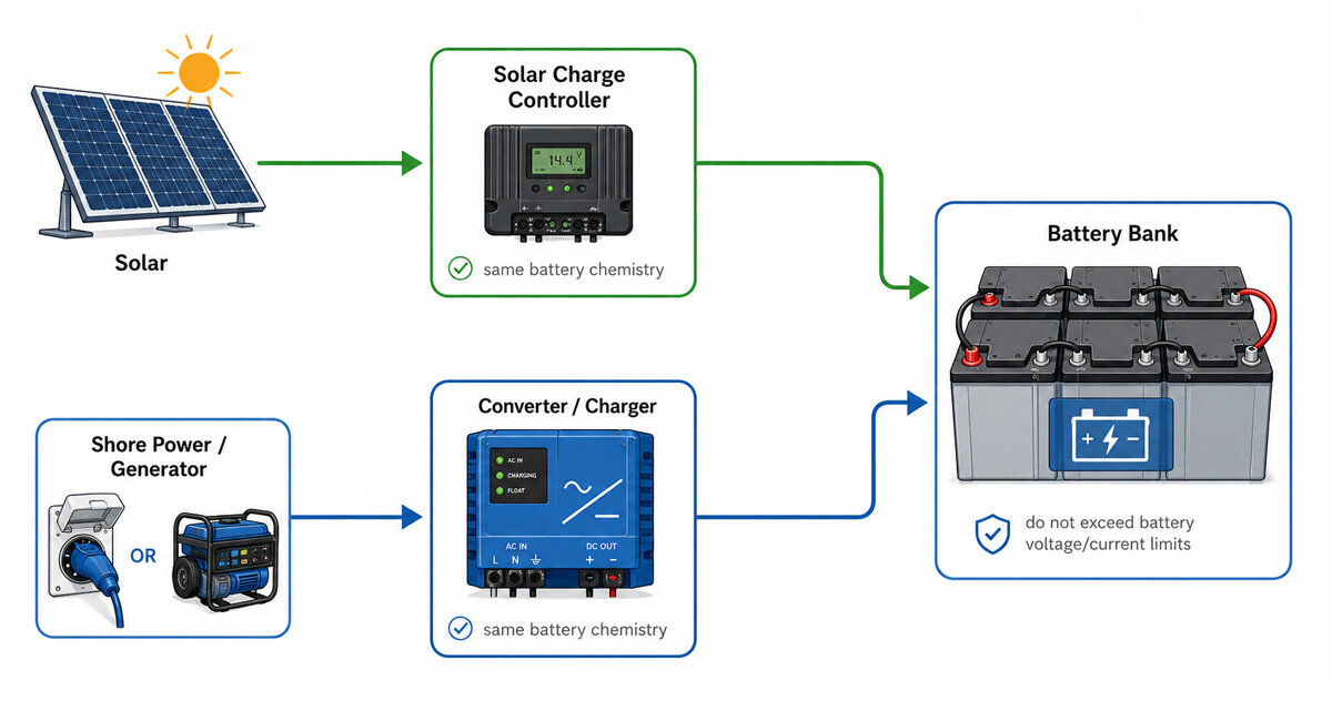
The converter/charger provides battery charging when an external AC source is available.
This is useful when solar production is low or when the system is connected to shore power or a generator.
The charger should be configured for the same battery chemistry as the solar controller.
When both charging sources are active, each device independently responds to battery voltage according to its charging profile. Properly configured chargers can therefore operate on the same battery bank without requiring the solar system to be disconnected.
The most important requirement is that neither charging source exceeds the voltage or charging-current limits specified by the battery manufacturer.
A converter/charger and an inverter are separate devices in many systems.
The converter/charger changes AC power into DC charging power.
The inverter changes battery DC power into usable AC power.
Some installations use a combined inverter/charger instead. This device performs both functions and may also include an automatic transfer switch.
If an inverter/charger is used, the wiring layout can be simplified, but its AC input, AC output, grounding, neutral bonding, charging capacity, and transfer-switch configuration must still be designed correctly.
The inverter should be selected according to the actual AC appliances rather than simply choosing the largest model available.
Two ratings matter:
Continuous power is the amount of power the inverter can provide for extended periods.
Surge power is the higher short-duration output needed when motors, compressors, pumps, refrigerators, or similar equipment start.
For example, appliances may operate normally at a relatively low wattage but briefly demand several times their normal running power during startup.
A pure sine wave inverter is generally the preferred option when powering sensitive electronics, motors, compressors, chargers, audio equipment, or appliances with electronic controls.
One of the most important design points is the current between the battery bank and inverter.
A 3,000W inverter operating from a 24V battery may require well over 125A at full load after inverter losses are considered.
This means the battery-to-inverter circuit often requires:
-
short cable runs;
-
large conductors;
-
properly crimped terminals;
-
a high-current fuse or breaker;
-
secure busbar connections.
Undersized inverter wiring can cause excessive voltage drop, overheating, nuisance inverter shutdowns, or serious electrical hazards.
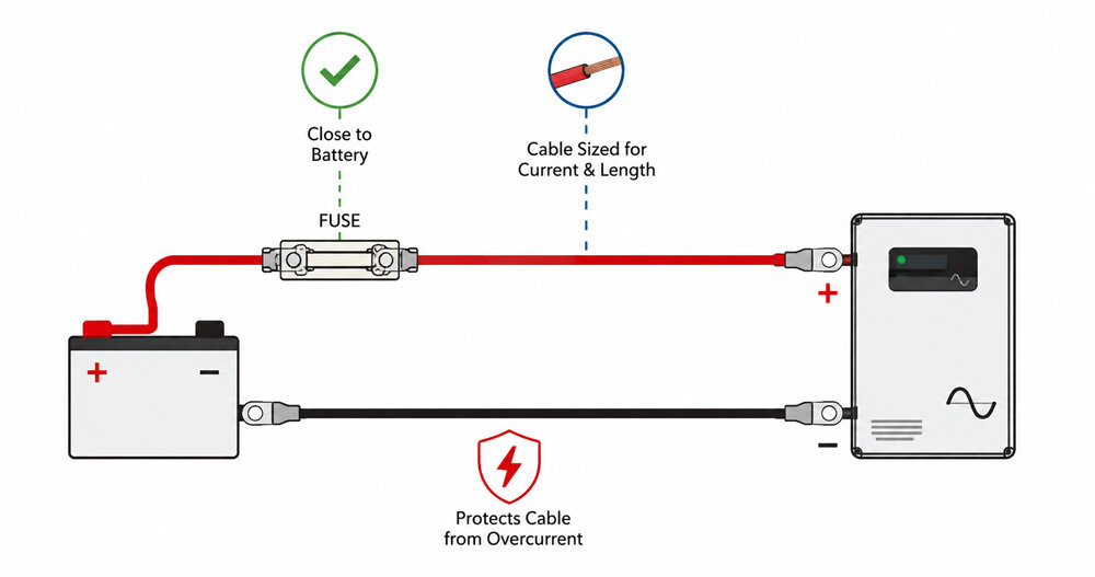
A fuse is primarily intended to protect the conductor.
It should not be selected only from the power rating of the connected device.
The cable must first be sized for expected current, cable length, installation conditions, temperature, and acceptable voltage drop. The overcurrent device can then be selected so that it protects the conductor without interrupting normal operating current.
High-current battery circuits require particular attention because a battery bank can deliver extremely large fault currents during a short circuit.
For this reason, battery-connected positive conductors normally require overcurrent protection close to the source.
Voltage drop matters more on low-voltage DC circuits than many installers expect.
Even a small voltage loss can become significant when an inverter is drawing high current.
Excessive voltage drop can cause:
-
lower inverter input voltage;
-
reduced efficiency;
-
overheating;
-
premature low-voltage shutdown;
-
reduced usable battery capacity.
Keeping high-current DC wiring short is often more effective than simply installing a larger cable after the equipment locations have already been fixed.
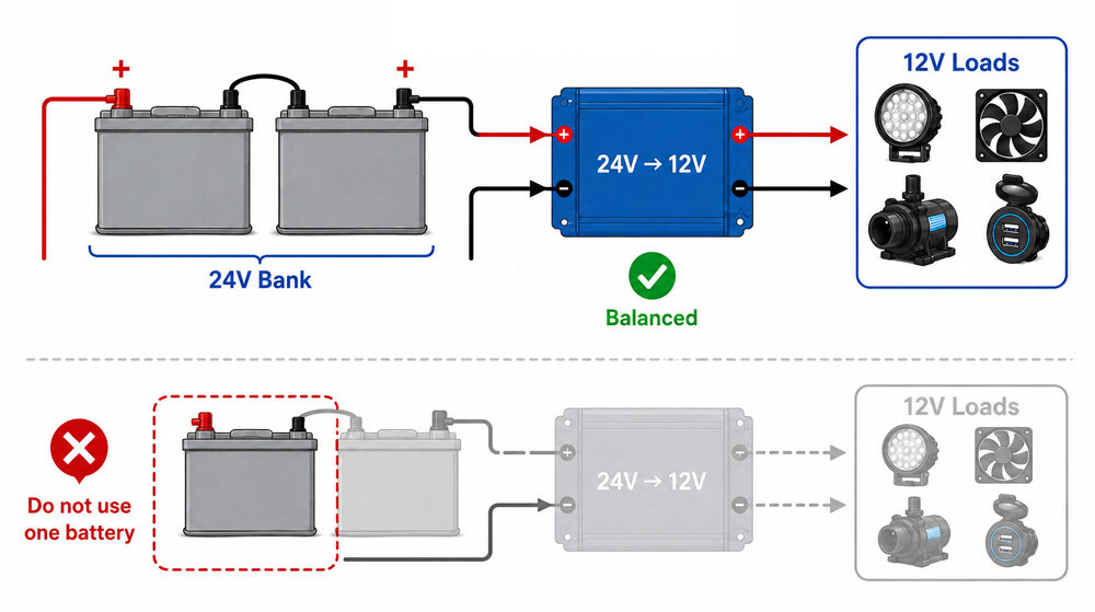
Many 24V systems still need to operate 12V equipment such as lighting, pumps, electronics, fans, or vehicle accessories.
These loads should normally be powered through a properly sized 24V-to-12V DC-DC converter.
Connecting a 12V load across only one battery in a series-connected 24V battery bank can create uneven battery loading and imbalance.
A DC-DC converter allows the full battery bank to remain balanced while supplying a regulated 12V output.
The combined charging capability of the solar controller and converter/charger should be checked against the battery's maximum permitted charge current.
For example, if the solar controller can supply 40A and the converter/charger can supply 50A, the battery could potentially receive close to 90A under certain operating conditions.
Whether that is acceptable depends on the battery specifications.
This is particularly important with lithium batteries because the battery-management system may disconnect the battery if charging limits are exceeded.
Grounding requirements cannot be determined only from the DC system voltage.
The correct arrangement depends on the inverter design, AC distribution system, shore connection, generator, transfer switching, installation type, and applicable electrical standards.
An inverter may switch the AC neutral internally or may require a specific neutral-to-ground bonding arrangement.
For this reason, AC neutral, protective earth, equipment chassis, and DC negative conductors should not be connected together simply because they appear to be common reference points.
The equipment manufacturer's wiring requirements and applicable electrical codes should be followed.
The best 24V solar systems are designed as a complete electrical network rather than as a collection of individual products.
Solar-array size affects controller current. Controller capacity affects battery charging. Battery capacity and discharge capability affect inverter performance. Inverter power affects cable size and fuse requirements. External charging capacity affects the total current the battery must safely accept.
Considering these relationships before choosing individual components produces a system that is safer, easier to troubleshoot, and better matched to the intended load.